25A 6V-50V 300W Sensorless Brushless DC Motor Driver Speed Controller NFP-BL50V300W
$13.5
$23.63
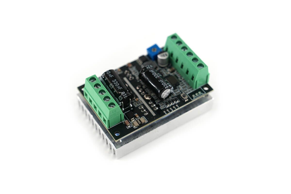
3-phase Brushless DC Motor Controller Technical Sheet BL50V300 non-inductive brushless motor driver is a high performance driver developed for Hall-free DC brushless three-phase motors with wide voltage and high current, featuring simple peripheral circuits, perfect functions, simple debugging, high driving efficiency, flexible application and wide applicability, etc. It only needs to be connected to the three-phase motor wires (UVW), and then can be realized as a motor control. Driver Model NFP-BL50V300W Driver Type 3 phases brushless type Operating Voltage 6V – 50V DC Control Way 0-5V / PWM Current 25A Power 300W Peak Current 35A Rated Current (12V DC) 25A Rated Current (24V DC) 12A Max Speed 80,000rpm Rotation CW / CCW Hall No Stall Protection Yes High Temperature Protection Yes Overcurrent Protection Yes Stop/Brake Function Yes MCU control Yes Low Voltage PWM Brushless Controller Outline Drawing Application areas: drone motors, water pumps, oil pumps, air pumps, power tools, small compressors, vacuum cleaners, storm fans, propellers, etc. High Power BLDC Motor Driver Functionalities Label Description Stop Default is high level (5V). Connect to GND to stop. Brake Default is high level (5V). Connect to GND for an instantaneous stop. Direction Default is high level. Connect to GND for reverse rotation. 0-5V / PWM Default is 0-5V speed control. 0V stops the motor; 5V is the maximum speed. Use a button to switch to PWM speed control. PWM frequency should be 1-10 kHz, with an amplitude of 3.3-5V. 5V Outputs a 5V voltage, with approximately 100mA current, for powering external devices. Sensorless Motor Driver External Potentiometer for Speed Adjustment Sensorless BLDC motor using an external potentiometer for finer control. Sensorless Electric Motor External PWM Speed Control Sensorless BLDC Motor Onboard Potentiometer Speed Control Button Operation Instructions: The button is used to switch between speed control modes. The default mode is 0-5V speed control (via potentiometer). Switch to PWM Mode: Press the button once briefly. The indicator light on the board will blink three times. This switches to PWM speed control mode, which takes effect immediately and saves the setting. The setting will persist even after power cycling. Switch Back to 0-5V Mode: Press the button once again briefly. The indicator light will blink once. This switches back to 0-5V speed control mode, which also takes effect immediately and saves the setting. Sensorless Brushless Motor Control Board Wiring Diagram ⚠️NOTE: Before using, confirm the motor’s voltage and power specifications to ensure they are within the module’s specified range. Connect the wires first, then power on. The module does not have reverse polarity protection. Reversing the power connection will cause permanent damage (be cautious). The power supply’s wattage must exceed the motor’s power requirements. For example, for a motor with a rated power of 100W, choose a power supply greater than 100W. Power calculation method: Power = Voltage × Current. For example, if the motor’s rated power is 100W and the rated operating voltage is 12V: Calculated rated current = 100 ÷ 12 = 8.3A. Therefore, the power supply’s current cannot be less than 8.3A. Keywords: dc brushless motor speed controller, brushless dc motor driver, brushless controller, bldc motor without sensors driver, sensorless motor driver